3-Way Switch Wiring Schematic : 3 Way Switch Wiring Schematic | Free Wiring Diagram : Take a closer look at a 3 way switch wiring diagram.. You simply need to have a good comprehension on various kinds of wiring and also their functions. It is really simple to attract a wiring diagram; Wiring diagram 3 way switch with light at the end in this diagram, the electrical source is at the first switch and the light is located at the end of the circuit. Pick the diagram that is most like the scenario you are in and see if you can wire your switch! The wiring diagram is normally made use of in electrical design to plan the positioning of electric circuits.
The wiring diagram is normally made use of in electrical design to plan the positioning of electric circuits. Pick the diagram that is most like the scenario you are in and see if you can wire your switch! What is a 3 way switch used for? Traveler wires are interchangeable on each switch. As we power this circuit, electricity will flow through the hot wire over to the second switch.
electrical - How do I wire 3 way switches where the power ... from i.stack.imgur.com Red and blue wires link traveler terminals of both switches. Diagrams shown on this page are simplified for clarity. The wiring diagram is normally made use of in electrical design to plan the positioning of electric circuits. As we power this circuit, electricity will flow through the hot wire over to the second switch. What is a 3 way switch wiring? This might seem intimidating, but it does not have to be. Wiring diagram 3 way switch with light at the end in this diagram, the electrical source is at the first switch and the light is located at the end of the circuit. The white wire becomes the energized switch leg, as indicated by using black or red electrical tape.
Pick the diagram that is most like the scenario you are in and see if you can wire your switch!
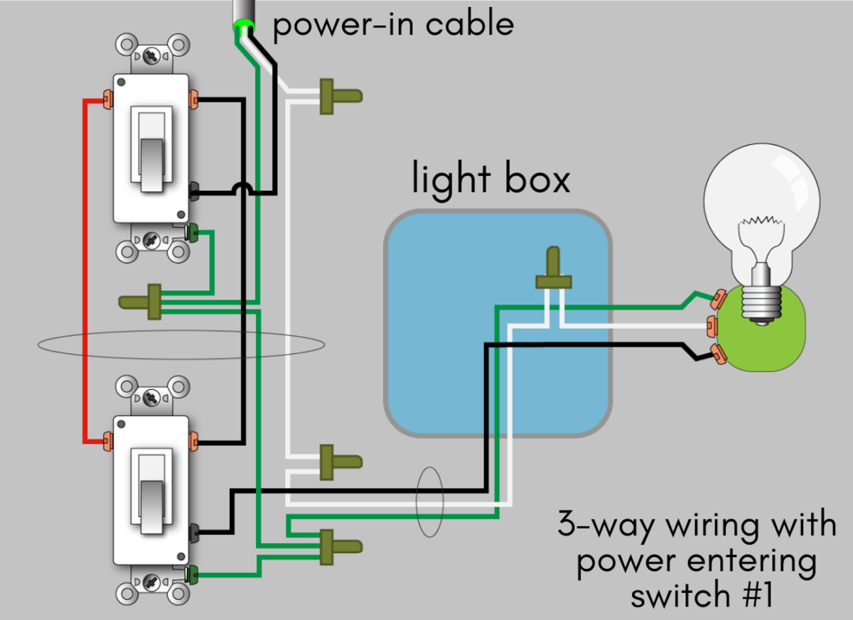
Apr 02, 2021 · by trafalgar d. It is really simple to attract a wiring diagram; The black and red wires between sw1 and sw2 are connected to the traveler terminals. This might seem intimidating, but it does not have to be. You simply need to have a good comprehension on various kinds of wiring and also their functions. Wiring diagram 3 way switch with light at the end in this diagram, the electrical source is at the first switch and the light is located at the end of the circuit. In this diagram, power enters the fixture box. The white neutral wires are connected together in each switch box. 3 way switch wiring diagram. Diagrams shown on this page are simplified for clarity. Red and blue wires link traveler terminals of both switches. As we power this circuit, electricity will flow through the hot wire over to the second switch. Traveler wires are interchangeable on each switch.
In this diagram, power enters the fixture box. Can a 3 way switch be used as a regular switch? This might seem intimidating, but it does not have to be. Red and blue wires link traveler terminals of both switches. Diagrams shown on this page are simplified for clarity.
How to Wire a 3-Way Switch: Wiring Diagram | Dengarden from usercontent2.hubstatic.com This might seem intimidating, but it does not have to be. You simply need to have a good comprehension on various kinds of wiring and also their functions. It is really simple to attract a wiring diagram; Traveler wires are interchangeable on each switch. As it goes through the red traveler, it will stop at switch number one. By correctly connecting two of these switches together, toggling either switch changes the state of the load from off to on, or vice versa. Apr 02, 2021 · by trafalgar d. The white neutral wires are connected together in each switch box.
The black and red wires between sw1 and sw2 are connected to the traveler terminals.
The black and red wires between sw1 and sw2 are connected to the traveler terminals. The black hot wire connects to the far right switch's common terminal. The white neutral wires are connected together in each switch box. The white wire of the cable going to the switch is attached to the black line in the fixture box using a wire nut. Diagrams shown on this page are simplified for clarity. As we power this circuit, electricity will flow through the hot wire over to the second switch. What is a 3 way switch used for? Apr 02, 2021 · by trafalgar d. 3 way switch wiring diagram. Take a closer look at a 3 way switch wiring diagram. Traveler wires are interchangeable on each switch. Red and blue wires link traveler terminals of both switches. By correctly connecting two of these switches together, toggling either switch changes the state of the load from off to on, or vice versa.
In this diagram, power enters the fixture box. Apr 02, 2021 · by trafalgar d. Can a 3 way switch be used as a regular switch? The black and red wires between sw1 and sw2 are connected to the traveler terminals. This might seem intimidating, but it does not have to be.
3-Way Switch Wiring Diagram from www.buildmyowncabin.com What is a 3 way switch used for? Wiring diagram 3 way switch with light at the end in this diagram, the electrical source is at the first switch and the light is located at the end of the circuit. The white wire of the cable going to the switch is attached to the black line in the fixture box using a wire nut. The wiring diagram is normally made use of in electrical design to plan the positioning of electric circuits. The black and red wires between sw1 and sw2 are connected to the traveler terminals. Can a 3 way switch be used as a regular switch? The black hot wire connects to the far right switch's common terminal. With these diagrams below it will take the guess work out of wiring.
It is really simple to attract a wiring diagram;
By correctly connecting two of these switches together, toggling either switch changes the state of the load from off to on, or vice versa. This might seem intimidating, but it does not have to be. The white neutral wires are connected together in each switch box. You simply need to have a good comprehension on various kinds of wiring and also their functions. Red and blue wires link traveler terminals of both switches. The switches may be arranged so that they are in the same orientation for off, and contrasting orientations for on. As we power this circuit, electricity will flow through the hot wire over to the second switch. Pick the diagram that is most like the scenario you are in and see if you can wire your switch! The wiring diagram is normally made use of in electrical design to plan the positioning of electric circuits. The white wire of the cable going to the switch is attached to the black line in the fixture box using a wire nut. The black hot wire connects to the far right switch's common terminal. With these diagrams below it will take the guess work out of wiring. Wiring diagram 3 way switch with light at the end in this diagram, the electrical source is at the first switch and the light is located at the end of the circuit.
Apr 02, 2021 · by trafalgar d 3 way switch wiring. The black and red wires between sw1 and sw2 are connected to the traveler terminals.


0 Komentar